Together with the motor supply cable and motor winding, the power output of the drive forms an oscillating circuit. Characteristics such as cable capacity, cable length, motor inductance, and frequency determine the maximum voltage in the system.
The AKD drive is able to protect the connected motor from overloading, if the parameters are set correctly and the thermal protection sensorA sensor is a type of transducer that converts one type of energy into another for various purposes including measurement or information transfer is connected and supervised. With Kollmorgen™ motors the valid data are automatically set by the internal motor database. With motors from other manufacturers the data from the nameplate must be entered to the referring fields in the motor view of the Kollmorgen™ setup software WorkBench.
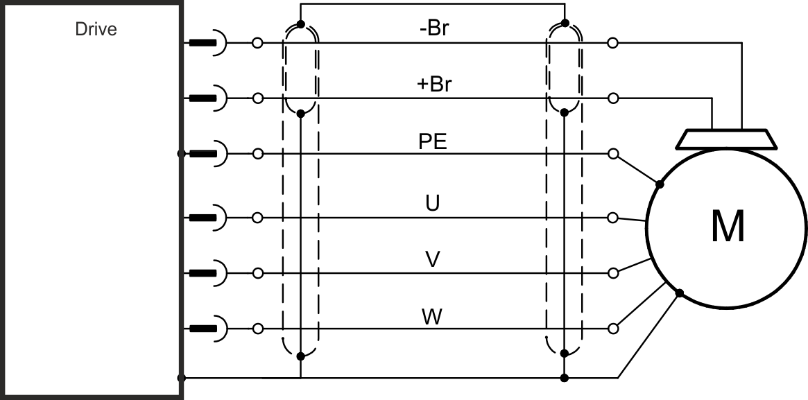
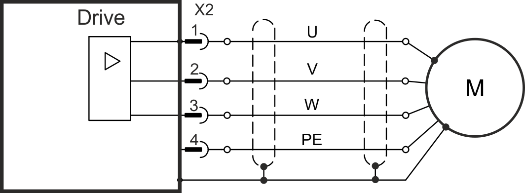
Cable length ≤ 25 m
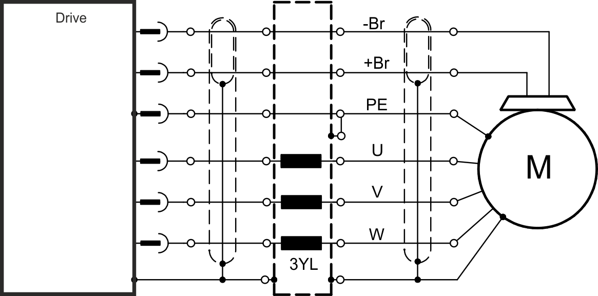
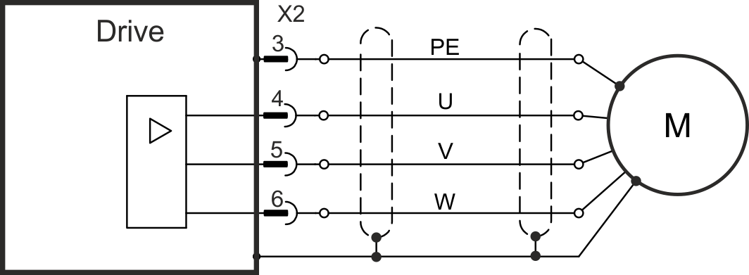
Cable length >25 m
|
|
|
|
|
Stay Connected with Kollmorgen       
|
Copyright © 2015 Kollmorgen™ |

|